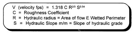
- Rate of Flow
All pipes have an internal surface roughness which exerts an opposing force to water flowing across its surface (as shown in the diagram below). The roughness of the pipe directly influences the rate of flow or carrying capacity of the pipe and is termed the ōCö FACTOR. Pipes with smooth interior walls, such as polyethylene (POLY) and polyvinylchloride (PVC), have C factors ranging from 120 to 140. Intermediate C values of 100 to 120 can be expected for new steel pipe, cement lined pipe, concrete cylinder pipe, and asbestos cement (AC). Low C values ranging from 60 to 100 can be expected for corroded pipe, tuberculated pipe, and concrete pipe. The relationship of pipe smoothness to flow capacity is as follows:
Since ōCö is directly proportional to V (velocity), two pipes of the SAME diameter but varying C factors can be expressed as:
V1 / C1 = V2 / C2
Assume that a tuberculated pipe with C1 = 80 is to be replaced by a new pipe with a C2 = 120, the increase in velocity would be equal to:
V1 / C1 = V2 / C2
V2 = V1 X 120/80 or
V1 X 1.5 (150%)
By changing the pipe, the flow velocity increased to 150% of the original velocity. The capacity of the new pipe is therefore 50% greater than that of the old pipe.
Corroded and tuberculated pipes REDUCE the system capacity to carry flow, depending on the pipeÆs internal surface condition. The FRICTIONAL head or pressure loss is directly related to the ōCö factor. Lower ōCö values increase pressure loss in pipes.
- Hydraulic Grade Line
Hydraulic grade line is a hypothetical line used to indicate the relative elevation of the total energy head (of the water) at any point in the pipeline. The concepts of the hydraulic grade line are illustrated below.

Under NO FLOW CONDITIONS, the pressure head available anywhere in the system equals the difference in elevation between the ground elevation and the hydraulic grade line elevation. In the "no flow condition" figure, the elevation of the hydraulic gradeline is LEVEL because there is no flow in the pipe and therefore no FRICTIONAL losses. The pressure available at houses A and B is equal.
Under flow conditions, the hydraulic grade line SLOPES in the direction of the flow with the slope equal to "S" in the equation V=1.318 R 0.63 S 0.54. For the LOW FLOW CONDITION, the "low flow condition" figure, the hydraulic grade line slopes moderately because the frictional losses are low. When demand is high, as depicted in the "high demand condition" figure, the hydraulic grade line drops more RAPIDLY because of the HIGHER flow velocities in the pipeline. Available pressure is consequently lower at high flow because the elevation of the hydraulic grade line is lowered.
Under severe demands, or demands exceeding the capacity of pipes to carry flows, VACUUMS (or pressure less than atmospheric pressure) can develop. These abnormally low pressures can leas to contamination of the potable water by BACKFLOW or BACKSIPHONAGE of contaminants into the pipe. The principle is illustrated in the "back siphonage" figure below. During normal flow, the frictional losses in the pipe are not severe enough to lower the hydraulic grade line below the ground surface. Und severe flows, such as may be experienced during a fire or watermain break, the hysraulic grade line drops rapidly, decreasing the pressure in the system BELOW normal operating pressure.
As shown in HIGH FLOW, areas B and C experience negative pressures. These negative pressures may be low enough to cause a backsiphonage action so that water flows FROM the service connections into the distribution pipe. If these waters contain any contaminating substances, the potability of of the water in the distribution main will be degraded proportionally. Sources that may introduce contaminants include industrial customers, hoses submerged in floor drains or waste tanks, waste storage tanks and other pollution sources that are directly connected to the distribution pipe. Backsiphonage prevention will be discussed later in this unit.
- System Pressure
System pressure is developed by using elevated storage reservoirs and/or pumphouses. Pressure in a distribution system is normally maintained between 280 and 550 kPa (40 and 80 psi). Under fire flow conditions, pressures in the distribution system should be greater than 205 kPa (30 psi) with minimum residual pressures of 140 to 205 kPa (20 to 30 psi) at the fire fighting location. Pumps, reservoirs, and appurtenances (valves, structures, etc.) are used to control pressures within distribution systems in order to maintain the system pressures within an acceptable range. In communities having little TOPOGRAPHIC RELIEF, the system is normally pressurized by elevated storage reservoirs or service pumps pumping water from treated water storage reservoirs. If the topographic relief is large, PRESSURE ZONES are used to separate lower regions of the community from higher regions. The concept is illustrated in the "pressure zones" figure below.

- Thrust
Pressurized water exerts a force equal to the pipe area times the pressure (F=PXA). At points where the pipe CHANGES DIRECTION, the pipe must be suitably supported and jointed to prevent the piping from pulling apart. In undeground piping systems, THRUST BLOCKS are used to restrain pipe and to distribute the thrust force to the adjacent trench walls. The thrust blocks are constructed at fittings, bends, connections, and at any location where the pipe changes direction. Typical thrust blocks are shown below.
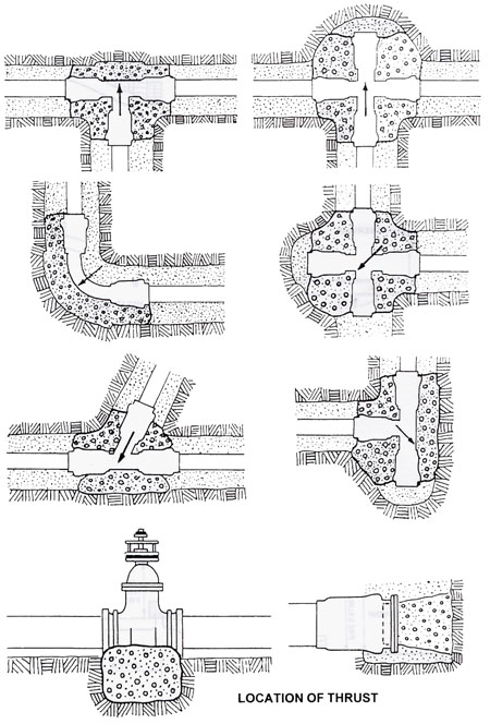
The most important aspect of thrust blocks is that they must be placed on the OPPOSITE side of the thrust exerted by the pressurized pipe. Constructing thrust blocks over or under horizontally constructed pipes provides little protection against thrust forces. The thrust blocks must be constructed so that the centre of the thrust block is aligned with the centre of the pipe. The bearing surface of the thrust block should extend above and below the centre of the thrust force. Refer to the figure below.

- Water Hammer
Water hammer is a form of pressure wave created by a rapid increase or decrease of water velocity in the pipe. Water hammer can develop if high capacity pumps are turned on or off too quickly or if valves are closed or opened too quickly. Water hammer exerts a tremendous pressure and can be destructive to pipes and pumping equipment. Pump control valves are usually used to start and stop pumps gradually. This helps to eliminate water hammer problems in discharge piping.
|